

Between 1966 and 1967 NASA sent five Lunar Orbiter spacecraft to the Moon. Their job was to survey the surface to help determine landing sites for the upcoming Apollo missions. In addition to their recon role, these spacecraft also contributed to the nascent scientific understanding of the Moon.
At the time that the images were taken using film that was actually developed aboard the spacecraft in lunar orbit, the ability to send back imagery was nothing like it is today. The photos were scanned much like news photos of the day and the data was sent back to Earth. The images were then printed out on photographic paper and used to construct maps of the lunar surface. In so doing a lot of data from the original photos was lost. Luckily NASA had the foresight to listen to the suggestions of project engineers such as Charles Byrne and stored the original data on analog tapes.
Some 40 years after these missions were completed the Lunar Orbiter Image Recovery Project (LOIRP) was begun with the intent of using refurbished tape drives and a complete set of original project tapes (over 1,500). Utilizing funding from NASA the LOIRP team was able to return the original drives to operation such that the data on the tapes could be accessed.
By adding modern computer interfaces and data handling techniques, the LOIRP was able to scan and record the data in ways that simply could not have been accomplished in the 1960s. As a result the images that were obtained had a much higher resolution and dynamic range than had been seen to date. Indeed, in many cases, these images often rival or exceed images taken by the Lunar Reconnaissance Orbiter which is currently surveying the Moon.
As clever as we thought we were, we were not the first team to tackle the issue of generating high resolution imagery. Someone tried to do much of what we were doing today – but did so with technology available in the 1960s. We were recently contacted by someone who had seen our project’s Facebook page. His name is Joe Watson and he worked on a project that used computer printers that worked like giant electric typewriters – but using varying sizes of squares instead of letters. With this system and a lot of creativity, Watson and his team created immense high resolution versions of Lunar Orbiter images from which topographic maps were made.
We had heard some vague stories about such projects but were unaware of just how audacious they were. So, in Joe Watson’s own words, here is the story of a precursor of the LOIRP.
Part 1 – My Story
In September of 1967, I had just emerged from a four-year enlistment in the U.S. Air Force, spent a few months getting a little homemade computer to work, and then landed myself a job as an IBM-360 computer operator at a company called Data Corporation in Dayton, Ohio. I was no expert on IBM-360 computers (in fact, I had never seen one before that one) but I was led to believe that this particular machine was a far hotter machine than most (at that time) with a full half megabyte of memory, the requisite IBM card reader/punch, a large continuous form printer, three disk drives (each the size of a small washing machine), a row of tape drives along one wall, and a special data storage device called a Data Cell with a capacity of 400 megabytes of mass storage. The Data Cell was so noisy, it had to be housed in its own small room.
I worked as a computer operator for only six weeks before changing positions to computer programmer. I have been writing software for a living ever since until I retired at the end of 2010. But during that brief six-week period, I was exposed to a number of amazing projects to which that computer was being applied. One of them involved the Moon.
The Lunar Orbiter satellites had been placed in low orbits around the Moon by NASA. They had taken pictures of the Moon’s surface and relayed them back to Earth. The images (probably as transparencies) had been brought to Data Corporation’s facility. A machine called a micro-densitometer had been used to optically scan the images and punch out its resultant data on 8-channel paper tape. The paper tape had been taken to an NCR-315 computer (also located at our company), read, and the data converted to a reel of magnetic tape. Then the magnetic tape was read by the IBM-360 and stored in the Data Cell unit.
A gifted programmer wrote some Fortran programs that read the image data, transferred a portion of it at a time to a disk pack, processed it, and printed it on our printer.
Printers in those days did not form characters with a matrix of dots. They printed more like the way a typewriter prints by having pieces of metal, each with a formed character, being very briefly stamped against an ink-impregnated fabric ribbon and pressing the ribbon against the paper. The image of the character is then left as residual ink deposited on the paper.
In this particular printer, those bits of metal with formed characters were attached to a recirculating chain, rather like a small bicycle chain. A special version of this character chain had been fabricated on which 63 of the character images had been replaced with a set of 63 squares of varying sizes. The smallest was just a tiny point in the center of the character image. The largest was a large square that occupied the entire character space. Through careful programming, the array of 63 square characters (plus space character) could be coaxed into printing an image with 64 grey levels. There were more complications involving the ribbon but they are not so important here.
Normally, continuous form paper is supplied in fan-fold form with holes punched down both edges of each page so the printer can guide and drive the paper using pins through the holes. The fan-fold paper is supplied all folded up in a box. The printer pulls the paper from the box, prints on it, and the resultant printout folds up again when it comes out of the printer. For our Moon pictures, the fan-fold continuous form paper was replaced by a large roll of plain white paper with no perforations or fan-folds. However, it did have the holes down both edges to allow the printer to manipulate it.
The roll of paper being fed into the printer proabably weighed a hundred pounds or more so there was no way the printer was going to be able to pull the paper from the roll without help, so a motor driven device unrolled the paper for the printer as it was needed. When the paper exited the printer, another custom built motor driven device wound the paper back up onto another roll.
There were 2 types of processing performed on the Moon images before they were printed and the processing was the real purpose for the project.
The first type of processing was contrast and edge enhancement. In areas where light and dark pixels appeared near each other, the light pixels were made a little lighter and the dark pixels were made a little darker causing details to stand out better.
This was pretty new stuff back an 1967 and I believe the people in charge were simply looking for enhancement parameters that yielded the best images they could produce. That is, they wanted images that showed the most detail without exagerating the image noise too much. While testing and tuning the system, a portion of an entire image would be printed on several strips of paper which were then taped side-by-side to form a paper image about 6 feet by 6 feet. The project gurus would examine the sample image and decide what to try next as enhancement parameters.
I remember one day when a series of these 6 foot square paper images was draped down along the top of an exterior wall of our building. Everyone in the building was asked to step outside to the parking lot for a few minutes to vote on which image appeared to them to reveal the most detail. The group included executives, secretaries, programmers, keypunch operators, and all other workers. Apparently, for a short time, we were all photographic image analysis experts but didn’t know it.
When the best enhancement parameters were thus determined, each full image was processed and printed on the strips of paper. The process of generating one entire picture took about 16 hours. The programmer and I would hover over the computer and printer during that time to be sure all went well. Afterward, I would go home quite tired but excited to be working on this clearly cutting edge project, even though my part was a very small one.
The next day I would run the output roll of paper through a machine to cut the holes off one side of the paper. Then I cut the paper into something like 20 strips, each about 20 feet long, and arranged them on the floor of a large open room. Taping all the strips together side-by-side yielded a single image on paper about 25 feet wide. Then we would roll the whole thing up and others would carefully take it away.
I never personally saw what happened to those pictures but I was told that they were unrolled on the floor of a building that had once been a church. Someone climbed up to a position high overhead and used a conventional camera to take photographs of the printed paper images. Those photos were then returned to NASA.
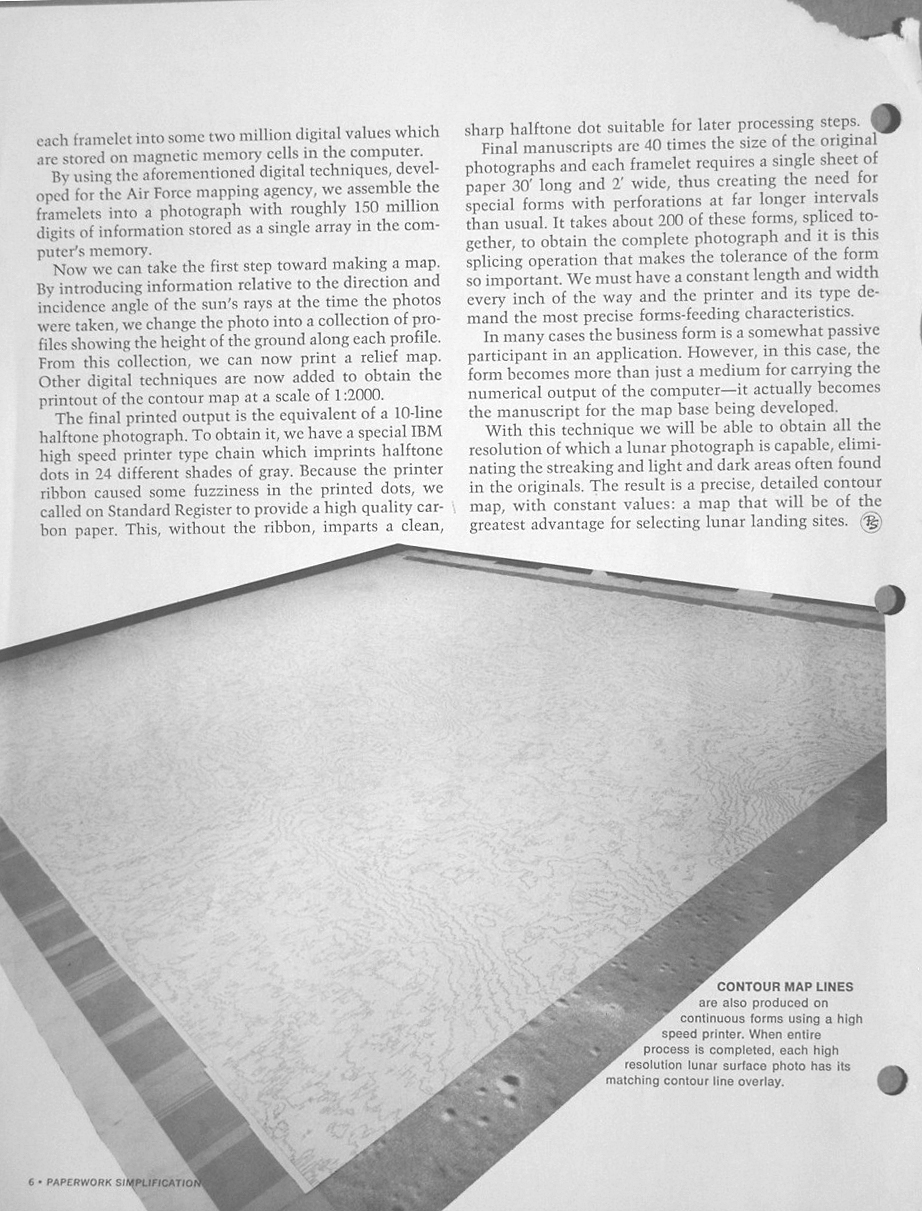
As I mentioned before, there were two types of image analysis done on the Moon pictures. In the second type of processing, the assumption was made that the Lunar surface was composed of material with a consistent reflectivity. By knowing the angle of the incident light from the Sun when the images were taken and evaluating each pixel’s brightness, one should be able to tell the angle of the Lunar surface at the point represented by the pixel. With suitable processing a countour map of the Lunar surface was then generated. It was printed and photographed in the same manner as the other pictures.
All of the resultant photographic images were then to be used by NASA to help select potential landing sites on the Moon for the Apollo project.
I also remember there being an effort where we tried to find the shadow cast by one of the Lunar Surveyor spacecraft that had previously soft landed on the Moon. As I remember, we were never able to find that shadow.
Less than 2 years later, with my trusty Super 8mm movie camera in hand, my wife and I stood atop a camping trailer parked on Cocoa Beach in Florida and I filmed the mighty Apollo 11 launch as it blasted off for the Moon. I have never been as impressed by any other event in my 66 years as what I witnessed that day. Nothing has ever come close.
When some test runs of the printed Moon images were being made, I was allowed to keep a portion of one image. I still own it today and looking at it always brings back memories of a very interesting time in my life nearly 45 years ago.
Part 2 – Paperwork Simplification Newsletter
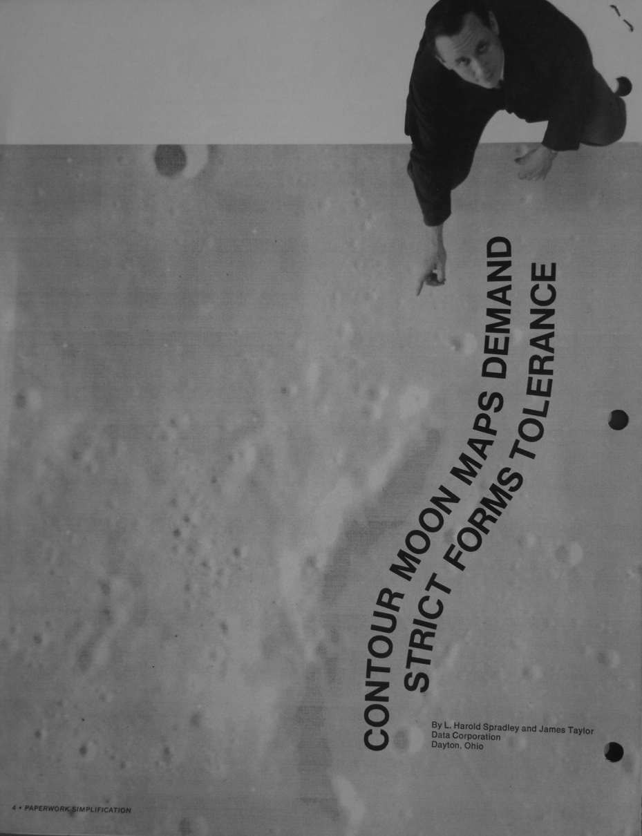
I believe the special paper handling equipment (that is, the power paper unroller) was provided by the Standard Register Company in Dayton, Ohio. For certain, that company did supply the unperforated continous paper roll. That company published a quarterly newsletter called “Paperwork Simplification”. The Fall, 1968 edition contained an article about the printing of the moon pictures at Data Corporation. The article was authored by L. Harold Spradley and James S. Taylor. Both men were quite sharp with great technical intuitive insight. Mr. Taylor was also my supervisor at the time. The man shown pointing at the top of page 4 is L. Harold Spradley. The young man appearing in the photos with the paper handling equipment is me. The young lady in the cover photo was our receptionist.
For some reason, in the article in Paperwork Simplification, the machine that digitized the Lunar image data is referred to as a Microanalyzer. However, I have found multiple incidences where that machine was referred to as a Microdensitometer and I remain convinced that was the proper name for it. I remember the people at Data Corporation pointing out that the aperture in that machine was created using a strong laser beam. I expect that alone was quite a feat in those days.
I have also noted that the article says that there were 24 different shades of gray in the printed images. I am pretty sure this is a typo and the real figure was 64 shades of gray.


Part 3 – Photos Of My Printed Paper Sample
I have included several photos of my printed paper sample. I unrolled a portion of it on my family room floor and shot it with a digital camera. If one looks closely in the Long Shot photo and easily seen in the Crater Close Up photo, you will see rows and columns of “9” characters imbedded in the data. These were some sort of sync characters that were removed by versions of the software used later in time. In the Pixels With Quarter shot, I attempted to make clear how large the pixels were in the printed image.
In early attempts to print the pictures, a problem arose when using a fabric ink ribbon in the printer. When a pixel was printed that was intended to print only a small area (such as a small black square in the middle of the character space), it would appear quite black. However, when a pixel was to be printed that was intended to print a large area (such as a large black square), it would appear much lighter in color because the same amount of energy from the printer’s print hammer was distributed over a much larger area. The solution was a special binary carbon paper used in place of the fabric ribbon. When struck by a print hammer, the pigment was transferred nearly in its entirety.
Therefore, all printed pixels were of equal blackness regardless of the area they used. As I recall, however, one drawback to this was that the pigment printed on the paper was much more likely to smear easily so careful handling was required. The printed sample that I have was printed with fabric ribbon. Hence, it can be seen that large pixels are more of a grey color than black.

![]()
Reference
Pictorial Output with a Line Printer, IEEE Transactions on Computers Feb. 1970 Author(s): Macleod, I.D.G. Volume: C-19 , Issue: 2 Page(s): 160 – 162